
In this post, we’ll cover how robots see, focusing on two of the most common kinds of sensors in robotics: cameras and LiDARs. We also provide image examples that help explain how a robot translates what its sensors see to data. So, how do robots see?
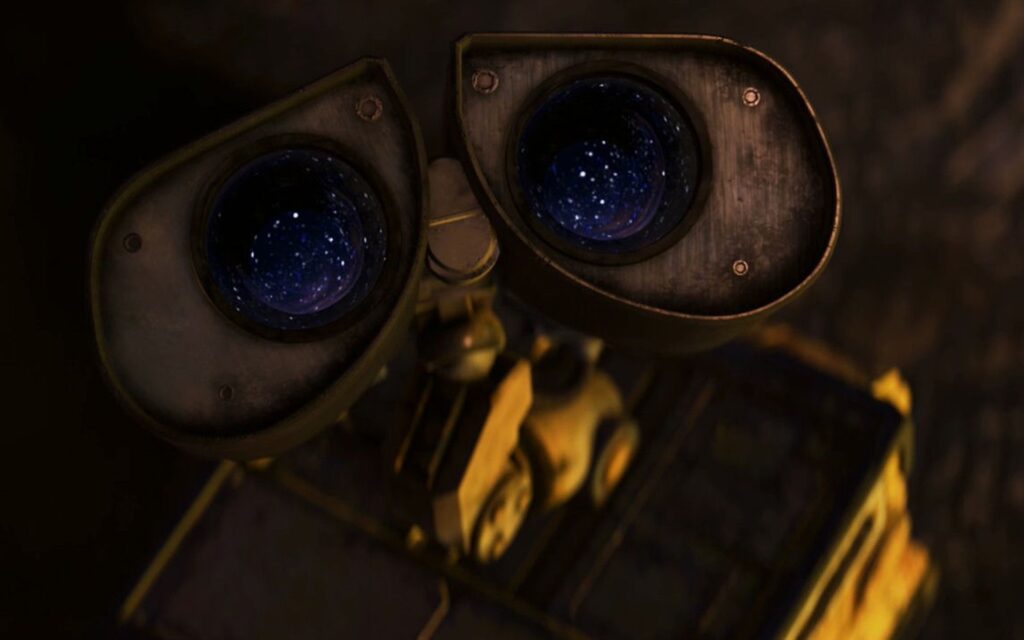
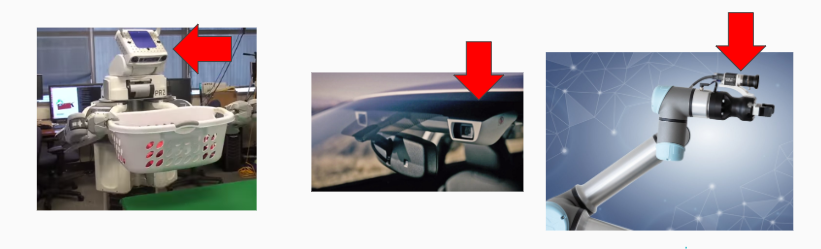
Cameras are the most common form of sensor that a robot can use to interpret information about the environment. Just how we can take a picture with a camera and then look at that picture and tell where a given object is in space (such as WALL-E in the picture above is above this text), a robot can also take a picture with a camera and then perform object detection to identify where something is in space, or what it is looking at. Many types of robots use cameras today:
How do robots see with cameras?
We know robots use cameras to “see”, but what does a robot actually see? A robot can “see” with a camera picture through a process known as computer vision. A robot takes a picture with the camera (which can be thought of a set of pixels in a matrix describing the resolution, such as 1920×1080. A matrix is a group of columns and rows:
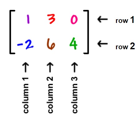
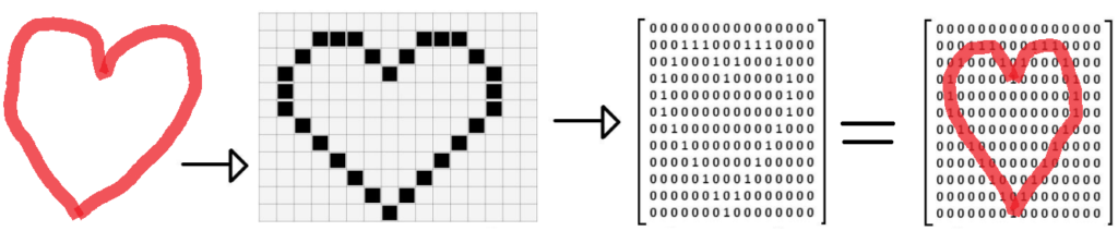
We describe matrices by the number of rows and columns of data they contain. Now that we know a matrix is a set of rows and columns, the common screen resolution 1920×1080 can be thought of as a matrix with 1920 rows and 1080 columns. We can represent an image as a matrix by converting it to a grid of 1920×1080 blocks, filling in each block with a color. To make things simpler, we can consider a black and white representation of an image, using either the colors white (0) or black (1). This grid representation, the second heart image below, is equivalent to a matrix that holds either a 1 or a 0, where a 1 represents the grid element (pixel) was filled in, while the 0 indicates nothing was there. As you can see in the fourth heart image below, we have a matrix with ‘1’s in the shape of a heart. Digital images store more detailed information in every grid cell, such as individual red, green, and blue color values, in what we call pixels.
As humans, we can then identify (classify) that a heart is in the matrix because we know what shape a heart is – curved, symmetric with two humps on top and a pointy bottom. This shape can be translated into a mathematical property, such that in the matrix, the column values with 1s should approach the middle column as the row increase (creating the V shape at the bottom). Such image processing mathematical properties are covered in more detail with image processing steps such as convolution, edge detection, object detection ect. Here is an example of an image with an edge detection filter applied (i.e, the matrix element values between neighbors differ by a lot where an edge is present):

The image containing the edges of the original is the result of a convolution of the original image – a mathematical matrix operation performed on the original image to transform it into one where just the edges are marked. The kernel defines how to modify (matrix multiply) the image matrix to get the output, and is used for operations such as blurring, sharpening, and edge detection among others. You can visualize a convolution on a matrix representing the image below:
In general, the image processing pipeline (sequence of events from getting a camera image to understanding it) can be summarized below:
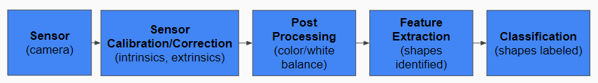
The sensor in this case is the camera, the signal light that the camera (sensor) lens absorbs and translates into a digital pixel matrix form, which is is changed to account for the camera settings, lense (sensor calibration), and standardized with color and light balancing (post processing). The processed image pixel matrix is then with the use of convolutions & matrix math operations modified to help identify things (feature extraction) in the image, from stop signs to boundaries (classification). Once a robot has processed a camera image as a 2d matrix and applied object detection to the image, it knows where a certain thing in the image is able to classify (identify) what an object is:
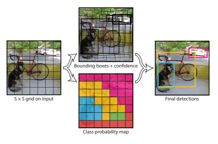
For the self driving car example, people and cars and traffic lights can be individually detected, with bounding boxes drawn around the detected shape to identify it in the image:
While cameras are great during the day to allow a robot to “see” objects in its environment and understand where and what they are, what if it was dark outside, or we need to gave a greater field of view? This is where LiDARs come in!
How do robots see with LiDAR?
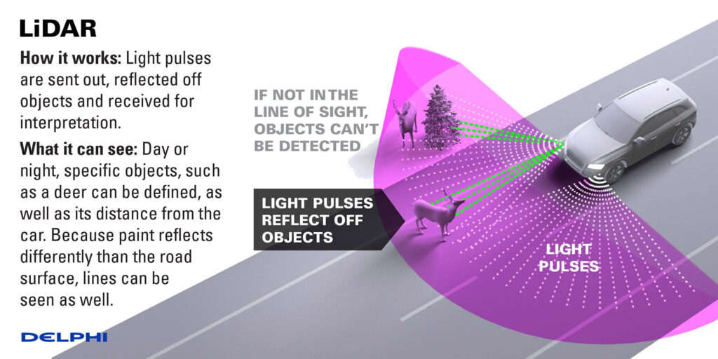
What is a lidar? A LiDAR (Light Detection and Ranging) is a type of sensor that sends light out into the environment and looks for the reflections that it receives back, to determine where things are. If there was nothing infront of a lidar to reflect light back, the lidar would not see anything as the light would never be reflected and return to it. On the other hand, based on how long it takes the light’s reflection to return to the LiDAR, the LiDAR knows how far the given object is from it as things farther away will take the light a longer time to travel to and reflect from. A liDAR is an active sensor, meaning it emits energy into the environment and then samples/listens for the responding reflection of that energy wave:

In the self driving car example, this is explained below:
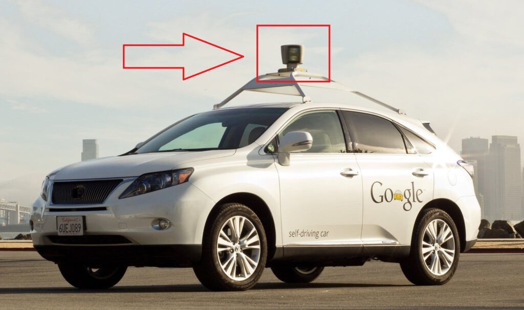
What does a LiDAR look like? While LiDARs come in all shapes and sizes, you may be familiar with seeing them atop of self driving cars. They are usually cone/round in shape, and you may be able to see or hear them spinning if you are ever close to one:
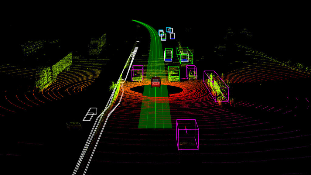
A LiDAR can provide full 360 degree coverage of the environment as it normally spins as it emits the light at a really fast rate, so that it can sample (get data from) the environment around it multiple times a second. In the self driving car example below, a 3D LiDAR shows the full 360 degree surrounding objects of the car. The black spots with no lines indicate no laser was returned from these places, as they were obstructed by closer objects that reflected the light. Based on the shape of the resulting cloud, we can classify cars and road signs:
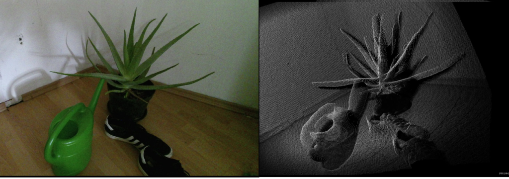
Just how a robot stores 2D camera information in a matrix, the LiDAR data is stored as a point cloud. A point cloud is the result of a sensor such as a Kinect that sends a lot of energy into the world (such as lasers) and then observes where they are around them to determine the distance to nearby objects. Each resulting “point” the sensor generates in the environment can be grouped together into a “point cloud” which describes the environment. An example point cloud looks like the following to a robot (real scene left, individual points representing scene right):
There is depth information associated with a point cloud, which a robot can use to determine the shape and distance from a given object. These sensors let the robot perceive the world around them, and understanding what is around a robot is known as perception. If we were to visualize the point cloud from LiDAR on self driving cars, it would look like:
There are some limitations to LiDAR in allowing a robot to see, which we discuss in our post on why robots don’t like shiny black floors. Now that we know how robots can see using sensors such as cameras or LiDARs, we can learn about how a robot decides what to do.


